Pegasus I, Pegasus II, Pegasus III, Pegasus IV, CF GPS Howto, #highaltitude Logs, Links, Ideas
I'm back! Finally got bored so I'd thought i'd do some ballooning!!!!
The plan is to work on a really accessible and cheap high altitude balloon payload using readily available products with only minimum soldering and assembly required. I'll update step by step so people can easily follow.
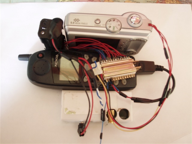
Basically we need a device that will take its position from a gps module, log it and then format it and then send it via sms back to us therefore informing us of its location allowing retrieval.
GPS ---> Flight Computer ----> Mobile Phone - - - - > Us
This device will be put into a payload box (probably made out of polystyrene) with a paracute and attached to a totex weather balloon and launched. The flight computer will also need to have a way of triggering a camera to take pictures at particular intervals (though a seperate circuit could be used that would require assembly etc.
Instead of the phone you could use a 434 mhz 10mW transmiter which would allow you to maintain contact through out the flight, see here.
The plan is to use a a linux based wireless router that is supported by OpenWrt (http://wiki.openwrt.org/TableOfHardware/) In theory you can use anyone of the routers that has 2 available serial ports. The two serial ports will be for the gps and also to connect to the mobile phone. There are a few other mods that can be added such as using the GPIOs to trigger cameras and even added an i2c bus therefore allowing a whole range of applications.
Parts list
Most of these parts have been ordered off ebay so will put some pictures up when they arrive and then start to work on step 2 - installing OpenWrt.
Well my Motoroloa WR850G arrived today so first i took a few pictures:
Connected by ethernet to my laptop running the motorola firmware, here
Removing the only scew, here
Disassembled here
Serial Port 1 location (ttyS0) here
Serial Port 2 location (ttyS1) on bottom of the board, RR93 (tx) and RR94 (rx) here For more infomation about which pins do what see here (Section 5.2)
Reflashing using the motorola interface here
Right so this is how to do it:
You now have a router that has an easily customised version of linux running. Take some time to explore the system both the web based interface and also ssh. E.g. running df -h will show you how much space is left:
root@OpenWrt:~# df -h
| Filesystem | Size | Used | Available | Use% | Mounted on |
| /dev/root | 896.0k | 896.0k | 0 | 100% | /rom |
| none | 7.0M | 116.0k | 6.9M | 2% | /tmp |
| /dev/mtdblock/4 | 2.3M | 752.0K | 1.5M | 33% | /jffs |
| /jffs | 896.0k | 896.0k | 0 | 100% | / |
What i've done as I only have one ethernet port (which is used for my internet) is to set up my wireless connection to the router. This was pretty simple as the stock OpenWrt runs a dhcp server so you with a bit of fiddling it should be easy!
I decided to start by adding the mobile phone interface to the router. Firstly I removed the DB9 serial connector from the data cable i had bought. Inside there should be three wires, Txd, Rxd and GND which I identfied by carefully opening up the actually phone connector and recording which pins attach to the wires. I compared this to this pinout here to work out what does what. I then soldered the appropriate wires to correct holes on the first serial port (picture here and pinout here)
Remember that TX on the router wants to go to RX on the phone and so on!
Now that the cable is connected its a matter of sorting out the software part. We are going to use gnokii and convinently there are binaries available. First you will need libusb which you can download here and then gnokii can be downloaded from here. Getting them onto the router isn't to difficult - I used scp to copy them to /jffs (writeable partion) so for example:
scp gnokii_0.6.14-1_mipsel.ipl [email protected]:/jffs/gnokii_0.6.14-1_mipsel.ipl
On the router to install all thats required is:
ipkg install /jffs/gnokii_0.6.14-1_mipsel.ipl
Next step is to move the console from being on the first serial port as it messes around with communication with the phone. Firstly makesure that you can easily access the router by either wireless or ethernet. I then changed the file /etc/inittab to use tts/1 rather then tts/0 - it will eventually change as tts/1 is for gps but for now this allows us to rescue via the 2nd serial port.
Now its necessary to find or write a gnokii config file which resides in /etc/gnokiirc, for example:
[global]
port = /dev/tts/0
model = 5110
initlength = default
connection = serial
bindir = /usr/local/sbin/
Now everything should be set up so turn on the phone and then type:
gnokii --identify
If everything has been correctly set up it should easily identify your phone.
Picture here
While trawling ebay I came across a batch of £10 Jupiter OEM GPS units so I quickly bought one. Conveniently there is an excellent site that details exactly how to set it up: Rockwell Jupiter GPS module. The first step was to get the correct socket for the 2mm pitch header - luckly rocketboy was getting some so he ordered me two 1x10 and then stuck them together.
First I connected the correct cables up, attached it to a 4.5v powersupply and attached an LED between Tx and Gnd and watched it flicker with what i assumed were the NMEA sentences being transmitted. Next it was necessary to connect it to the second serial port on the router, this is quite hidden as described earlier Rx is at RR94 and is the pad closest to the network switch rather then all the led lights. I soldered the Tx wire from the gps to here and also added a common ground (used one of exposed point where the screws go).
It was next necessary to set up the serial port, firstly I had to comment out the line in inittab which was running the console through /dev/tts/1 (second serial port) (I had changed this from the first serial port when I added the phone, it does mean no that there is no console access but wireless is working so well i'm not to worried. - could perhaps added a bit of code that after a while it reverts the console back onto one of the serial ports). Some software is necessary, setserial (here) and stty (here, its a gzipped binary which will need to be moved to /jffs/ and also its permission changed chmod 777 stty will do) Next it was necessary to give the serial port an IRQ value with the command:
setserial /dev/tts/1 irq 3
Next the speed of the port needs to be set:
stty -F /dev/tts/1 speed 4800
Might as well have these commands run at boot so a script in /jffs/etc/init.d/ called S99custom and containing:
#!/bin/sh
setserial /dev/tts/1 irq 3
stty -F /dev/tts/1 speed 4800
If all goes well it you
cat /dev/tts/1
Magically NMEA strings will appear on your console!
Will post pictures later.
Sadly due to work constraints (I'm back at uni) its going to be a good while until I'm in a position to have a payload to fly perhaps after Christmas. Also a lot of the reason why I'm delaying in building a payload is that I'm not that inspired - All Pegasus IV would be would a repeat of previous missions. In the mean time I hope to do some reading around the area and come up with some new ideas and applications. Feel free to email me if you want to ask questions etc! The people to watch are definitly the CU Spaceflight group and their Nova missions - I hope to go along to some of their launches so if you are in the UK definitly get in touch.
Pegasus IV will build upon the success of Pegasus III and recycle all the parts. In addition a 6MP camera will replace the original 3MP camera. The plan is also to finally get some sensors onboard either via the 4 a/d convertors on the GPSstix (requires a driver to be written, any volunteers?) or via another method such as i2c or even the spare serial port. I'm interested in the rate of spin of the payload at all altitudes so i'm looking at a 3 axis accelerometer and also a digital compass. I'm working on a more reusuable case which might take on a new shape. While this may seem like not much of a change from Pegasus III its the beginning of a new stabalising system I'm working on and so the flight could be regarded as an info gathering mission.
I'm thinking of Pegasus IV being the command/communication module for further missions. Instead of having to resolder devices etc I'm going to add a "breakout" cable (perhaps a 40 pin IDE cable) from the key connectors on the GPSstix which then can easily be interfaced with (as well as allowing the gumstix to be easily seperated from the payload). The module itself will then be easily attached to a larger payload (perhaps Pegasus V) but should be able to fly on its own.
Pegasus IV will be made up of:
Got
To Get
Finished wiring up a DB25 connector which brings out 2 serial lines (HWUART and BTUART), i2c and 7 GPIOs. Mainly for my own memory these are my pinouts:
| HWUART Rxd | 24 - Red |
| HWUART Txd | 11 - Blue/Black |
| GND | 12 - Blue |
| BTUART Rxd | 13 - Blue |
| BTUART Txd | 25 - Red |
| SCL | 10 - Red |
| SDA | 23 - Blue |
| LDD | 345678910 |
Have connected up the phone, again you only need Rxd, Txd and Gnd wired up (remember that Rxd on the phone needs to go to Txd on the gumstix). A pinout for the phone connector can be found here. As its connected to HWUART its necessary to change the gpio settings on the gumstix with:
modprobe proc_gpio
echo "AF1 in" > /proc/gpio/GPIO49
echo "AF1 out" > /proc/gpio/GPIO48
Its will now be on /dev/ttyS3 and can be tested with:
./gnokii --identify
I've also had to move my resistor which is attached to the gps module on the GPSstix to another point of Vcc to allow access to the i2c pins. At present the gps is working well on STUART (/dev/ttyS2)